The clock should feed into the 74LS163 because 0-9 is the LSB (least significant bit)
The clock signal for all 3 JK flip flops (74LS76) should be triggered from the output of the 74LS163 whenever the LOAD is NOT triggered for the 74LS163.
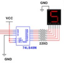
Use 74LS48s with 220 Ohm resistors to connect to the 7 segment displays (this circuit can't use the BCD displays, it requires 7 segment displays) like this.
The reset switch connects to 2 places:
The 74LS163 is triggered to go back to 0 when the output reaches 1001 ( 4-input NAND gate)
The JK flip flops are triggered to go back to 0 when the output reaches 110 (3-input NAND gate) AND the reset switch is set.